
Introduction
If you find technical discussions boring or you don’t think computers should have anything to do with heritage steam projects, please skip this page. What follows is a discussion on the design of locomotive boilers using a design by analysis method in addition to design by rule. This page has animated graphics and will take a little while to load fully - once cached locally the images should animate correctly.
Design by Rule
Boiler Codes such as BS2790 and the ASME Power Boilers Code define a set of rules which will lead to a safe boiler design. The rules were developed through a combination of mathematical formula and are a distillation of the experience of what has worked satisfactorily for many years. However the most recent versions specifically exclude locomotive style boilers. It could be argued that this does not matter for heritage steam projects as the new boiler would be a copy of the original, which acts as an extensively tested prototype. To counter this, financial constraints or, as in our case, a desire to minimise weight, drive continued development of locomotive boiler design.
Design by Analysis
Ideally an engineer should be able to calculate the stresses in each part of the boiler using mathematical equations. This is entirely possible for simple shapes. For example, the maximum hoop stress in a boiler barrel is calculated by multiplying the radius (half way between the inside radius and outside radius of the barrel) of the boiler by the internal pressure and dividing by the plate thickness. The design codes include simple equations, augmented with practical experience, for barrel stress, plate bending and stay loading. Unfortunately a locomotive boiler is much more complex than a simple cylinder and there are no mathematical equations that cover all the geometric shapes contained within it.
Modern computer aided engineering software can analyse a representation of a structure by breaking it down into discrete mathematical lego bricks. The software understands how the external forces affect the stresses in each brick (the general name used is finite element rather than brick) and how each element affects its neighbours. Modern cars, commercial airliners, mobile phones, oil refineries – the list is endless – will have been designed by analysis even if they are certified by design rule.
Analytic approaches to pressure vessel design, specifically the use of Finite Element Analysis (FEA), were developed well after the “age of steam” was over. The last UK main line steam locomotive for British Rail was produced in 1960 and at that time computers were shrinking from the size of a room to the size of a large refrigerator. A state of the art computer in 1960 was 100,000 times slower than the lowliest of home PC’s today and cost about a million pounds in today’s money. FEA was in its infancy and was really only developed in the 1960’s and 70’s.
Finite Element Analysis of Consuta's new Boiler
To save weight, Consuta's new boiler will use thinner plate than the original and has more steam space above the fire box crown. These design requirements may lead to higher stresses and we have taken the opportunity to perform a lot of engineering simulation using a Finite Element Modelling system.
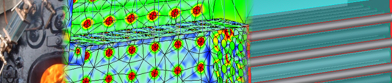
The initial design used vertical stays to support the fire box crown. An early analysis, shown below, indicated some high stresses and distortion in the areas not supported by these stays.
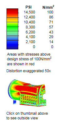
The diagram's that follow warrant some explanation. The 1st, 4th and 5th are interactive; clicking on the main image will start an animation which shows an 50x exaggeration of the way the boiler flexes as it is brought up to its operating pressure (170psi) and down again (To save your cpu, click on the moving image to stop it again). The viewing angle on all of them can be changed by clicking on the small thumbnail to the right of the main image. The colours on the surface of the boiler are a fringe plot of the maximum principal stresses over the surface of the model. The top level, coloured red, is set to show areas that exceed either a nominal design stress of 14,500psi (100N/mm2) or a nominal yield stress of 39,000psi (250N/mm2).
All that distortion and red colour look rather scary but it is important to remember that this is just a simulation and many approximations and assumptions have to be made when building the simulation model which has to be much simpler than the CAD model to be able to run on a modest sized computer.
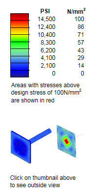
One very visible example is the red areas around each stay attachment point on the half boiler models on this page. Their attachment stresses are exaggerated by the type of finite elements used (known as shell and beam elements). The stays (beam elements) assume they are spot welded to the wrapper (shell elements). If the weld profile is modelled accurately using solid elements, as shown immediately below, these stresses are shown to be at much lower levels. It would however be impractical to model the whole boiler in solid elements with the computer resources available.
The shell elements used also show bending stresses in a confusing way. Close inspection of the animated bread slice models below shows a more accurate picture of which side the bending stresses act.
The actual distortion is only 0.13 of an inch or 3mm and the stresses predicted by the analysis software are generally below the yield stress of a typical boiler plate steel. The results (not animated) shown below are for the same conditions as the picture above but red has been reset to show areas above the yield point. You can see that most of the areas are below the yield stress and it is quite likely that the boiler would work well but perhaps suffer from some premature stay failures at some later stage in its life.
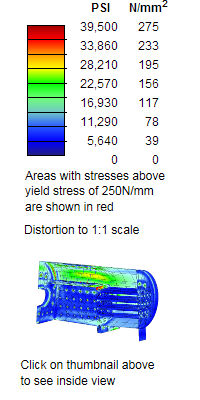
Interestingly the top row of side stays are often of a larger diameter on many locomotive boilers and many have an extra row of horizontal stays above the firebox crown. Both of these areas are shown by the analysis to have some of the highest stresses.
Most locomotive boilers were designed before the advent of computers. Designs were typically only altered when something broke or bulged too much. Anything above the design stress but below the yield stress was likely to go un-noticed until some sort of fatigue failure occurred (stays being a prime example). It is also interesting to notice that the high stress areas are often some distance from the design problem that is causing them. This is evident at the rear corner of the wrapper plates.
We could reinforce the new Consuta Boiler with some extra horizontal tie bars but this will add weight. The initial full boiler analysis showed that most of the distortion occurred in areas connected by the crown stays so a more detailed model was build to represent a vertical "bread slice" through the firebox.
This model highlighted the lack of support of the shoulders of the wrapper plates, allowing the horizontal component of the internal pressure to push them out. This can clearly be seen in the left-hand animation below.
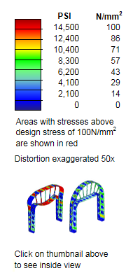
This could be reduced by adding a horizontal stay above the fire box, but to save weight the analysis software was used to find a set of stay angles that provide adequate support without the need for extra stays. This is shown in the right hand animation above.
The stay angles in the initial full analysis model were then modified to those found with the bread slice analysis to provide a very much better stress distribution as shown below.
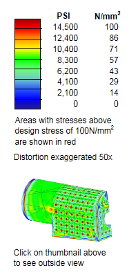
There is now very little movement in the boiler. The benefits of proper stay positioning are visible a long way from the wrapper. For example the junction between the throat plate and foundation ring shows less stress because the outer shell of the boiler is less distorted
There is now very little movement in the boiler barrel but some further work could be done to balance the stay tubes and long stays to reduce back head and smoke box tube plate distortion